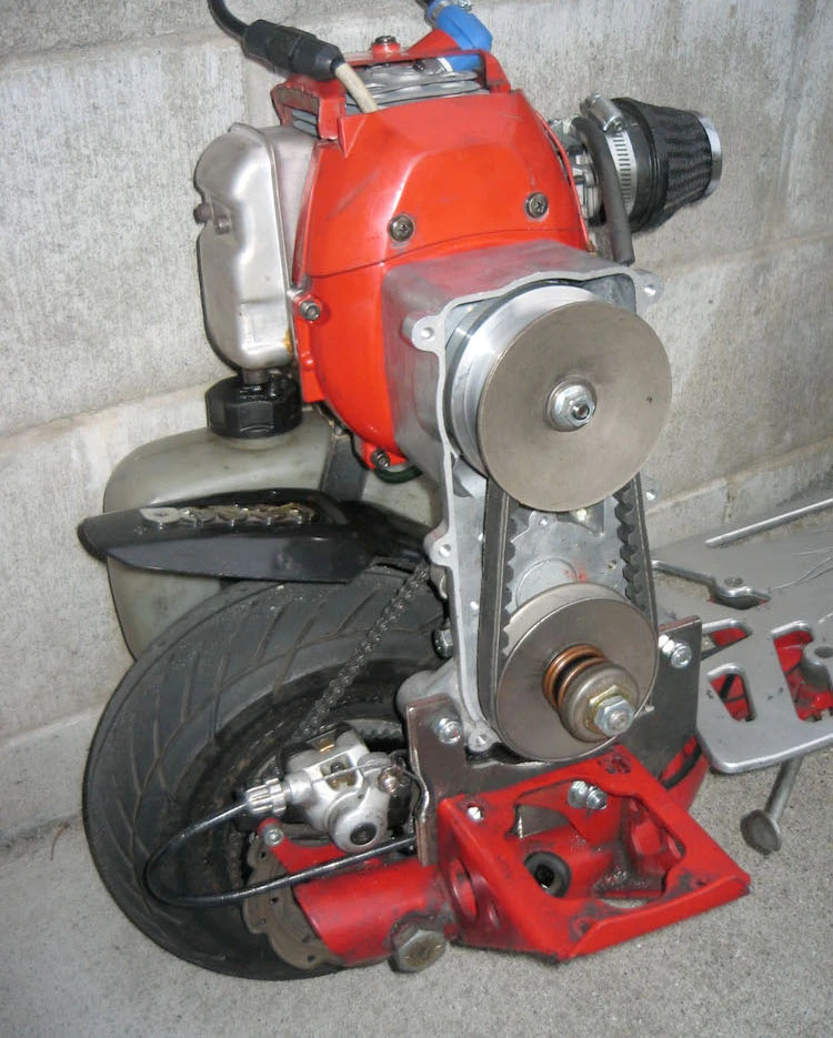
A continuously variable transmission (CVT) is the holy grail of performance for two stroke engines. This is the case for two reasons: the two stroke engine's narrow power band and the CVT's ability to keep it in that power band. Without a variation in the gear ratio, gas scooters experience a very limited range of effective drive ratio. Even though the larger two stroke engines are very powerful, that power is not properly harnessed. What a CVT does is that it allows the engine's RPMs to stay within the power band through the entire acceleration of the scooter. This effects low-end power and high-end speed drastically.
This guide will show you how to modify a Goped GSR40 with a pocket bike continuously variable transmission. This guide is based on the original GSR40_CVT project.
Tool and supplies[]
- Tools
- Hack-saw, rotary tool or ban saw
- American socket and wrench set
- Drill with 5/16" bit
- Parts
- X2 Ninja pock bike CVT
- #25 chain 25 tooth, 6 splined pinion (to make the transmission compatible with the scooter chain)
- Bolts? Washers?
- Materials
- 5 3/8" washers (spacing the rear sprocket and rotor)
- 5 5/16" thick bolts and lock nuts (mounting the CVT and engine support)
- 13 5/16" thick washers (shimming the CVT and engine support)
- 6 x 3 3/4 x 1/4" thick steel sheets (to build the CVT mount with)
- 9 x 1 x 3/16" steel bar (to build an engine support with)
- 4 x 4 x 1/8" steel angle bar (to build engine support attachment)
Cutting the CVT mount[]
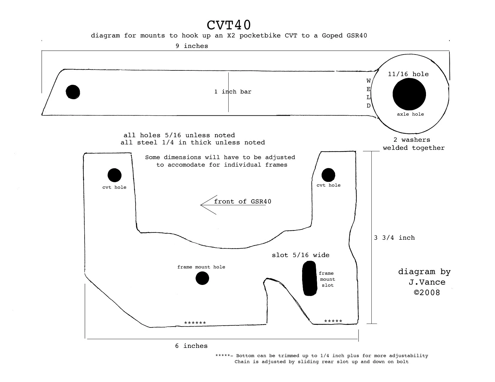
Diagram of fabricated parts
As described by the diagram, you'll need to cut CVT mounting plate, an engine mounting plate and an engine support out of the steel the you have. In the diagram, the engine support has two washers welded to the end of a steel bar to form the engine support axle connection, but that step is only necessary if the support bar is not already wide enough to support the axles hole.
The diagram also shows two holes cut into the base of the CVT mounting plate for it to bolt up to the Goped GSR40 engine mount. It is a good idea to drill the GSR40's engine mount before drilling the steel plate. That way, you can us the engine mount holes as a guide for where to drill into the plate.
Once you have the CVT mounting plat constructed, you'll want to mount it up and to have a look at how the sprocket and pinion will line up. (It is a good idea to mount the #25 chain pinion attached to the CVT at this point) You might have to do some shimming[1] in order to get the gears to line up. You'll want to make sure to do this before you proceed so that you don't have to re-cut anything later.
Cutting the engine support[]

In order for the CVT and engine to be properly supported over the back tire of the scooter, a support will need to be made for the pull-start side of the engine. Luckily, the bottom mounts of the Zenoah G43L-D make this process easy. You'll need to cut a piece of angle bar long enough to drill holes that line up with the pull-start engine mounts of the Zenoah G43L-D.
Next, you will need to cut the support bar at the right length so that the axle can pass through one end while the other reaches far enough to meet the engine mount's angle bar. The support bar will need to be drilled on both ends. One hole will be for the axle to pass through while the other will be for a connection to the engine mount.
Constructing a chain tensioning system[]
Since it will be important that we can adjust the location of the CVT in relation to the rear sproket in order to adjust the chain's tension, we will need to build that adjustability into the mounts we've made.
The first thing we need to do is elongate our hole in the CVT mount so that the mount will be able to pivot. We'll want to elongate the furthest backward hole so that the mount can pivot on the from hole. The best way to do this is to attach the plate to the engine mount with only the front bolt in place, and with a magic marker, draw into the rear hole as you rotate the plate on the front bolt.
Now, you'll want to clear out a little bit of the material you've marked on the engine block so that we has some play in the final setup.
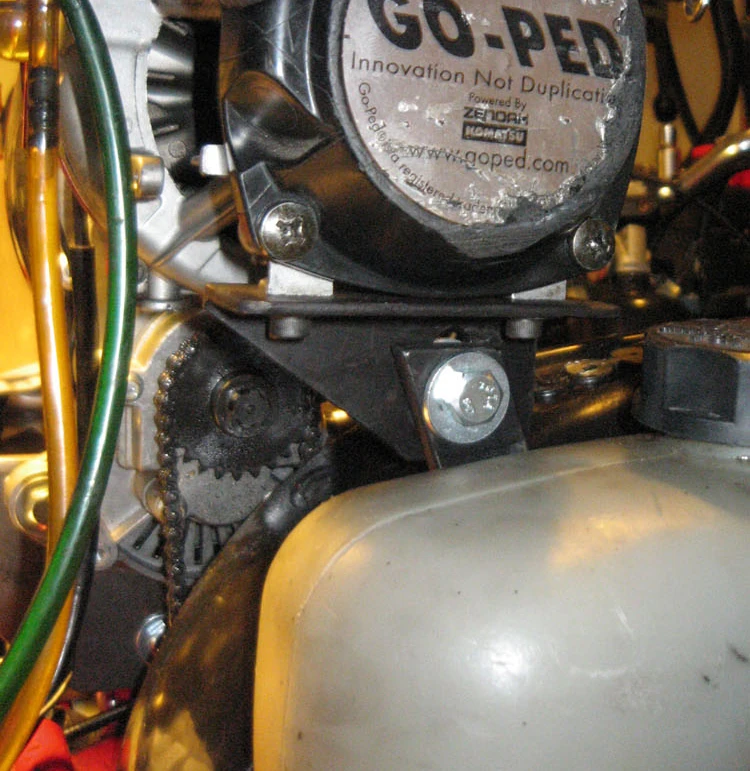
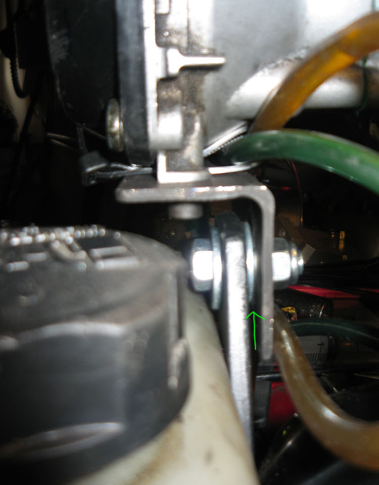
A similar process must also be performed on the engine support. In this case, we will simply elongate the hole in the engine mount angle bar. Since this hole will not be rotating, you can safely just elongate it vertically in relation to the engine. This picture is a good example of the result of this step.
Assembly and shimming[]
Some washers will need to be added to the construction in order to assure that the chain transmission is aligned and that the brake is spaced correctly for the caliper.
The engine mount. Add spacers to some of the longer length bolts that hold the CVT to the fan cover. If you use the standard length bolts, they won't be long enough, and you can strip out your clutch mount holes. If you use the longer bolts, they will hit the flywheel with no spacers.(no pictures of this right now...)

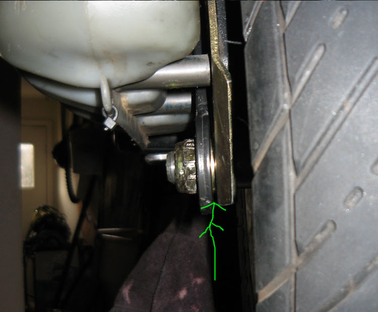
The support bar. Grind the weld down on the inside of the welded washer axle support to be flush to the axle support bar (if you opted to weld washers into place). Add a very thin axle washer between the fender axle mount and the axle support bar for a little extra space. You also should loosen the top gas tank support to fit the bar thru. Tighten it afterwards, or maybe even space the whole gas tank off the side by 1/8 to 1/4 inch with washers or spacers.


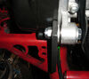
The engine mount. Add a washer between the angle steel engine support and axle support bar for a good fit. Without it, it would put undue stress on the case.

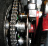
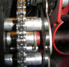
The CVT. Use washers to position the side to side spacing of the CVT to plate connection. This will help you align the sprockets. 1 washer between the CVT and plate on each hole should be sufficient.

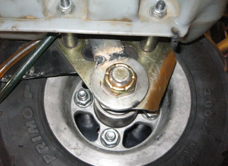
The sprocket. Add 4 washers between the rear sprocket and brake rotor to help with spacing and chain alignment.

The brake rotor. Add a washer between the frame and 1st axle spacer. You'll need to re-adjust the brake caliper afterwards.
Exhaust Options[]
Since this modification turns the engine around, it can limit the possibilities for mounting tuned pipes.
- ↑ Adding washers to the mount to space things correctly